
During EMC testing it is important to monitor the device under test (DUT) without interfering with the measurement during emission tests. On the other hand, the monitoring system has to withstand the high field strengths during immunity testing. Audivo provides the latest technology of EMC hardened audio and video system with high resolution and control via network and documentation.

Eretec provides the global manufacturer, maturo’s electromechanical positioning systems for EMC, automotive, radio and radar measurements. All specifications can be individualized according to customer requirements and a variety of customized positioning system is provided. Eretec’s experienced engineers install at the site and offer very prompt maintenance services whenever issues are raised.
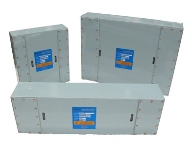
MPE is formed in 1925 and his comprehensive standard suite of core products spans high performance feedthrough capacitors ; high current power, telephone, data & control line filters, through to the latest HEMP range of protection filters. Outside of this core ranges, MPE have a catalogue in excess of 20,000 designs that can be drawn upon to fulfill more ‘specialist’ requirements. In addition, MPE’s ability for rapid development and prototyping ensure that any new design requirements can be fully met.
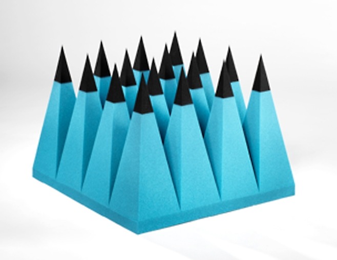
As the largest chamber provider in Korea, Eretec also supplies absorbers, one of essential items for EMC and Antenna chambers. Bespoke design and proposal are possible optimal for the customer’s purpose and specification requirement.

RF/EMC/EMP protection doors fully meet the demands both from commercial and military. Prompt maintenance service is one of the strong points of us.
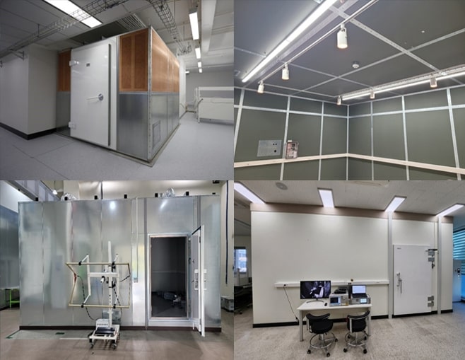
Provide reliable and optimal test condition by shielding electromagnetic noise from 14kHz to 40GHz.

The EMP Design & Build Process provides a complete EPC (Engineering, Procurement, Construction) solution for EMP protection facilities. The process covers all stages: from initial Analysis and Detailed Design (defining critical POEs) through Construction, culminating in rigorous Performance and Acceptance Testing (SE/PCI/SELDS) by authorized bodies. The scope includes comprehensive EMP Shielding, Critical Communications/Electronics, and Essential Mechanical Systems.
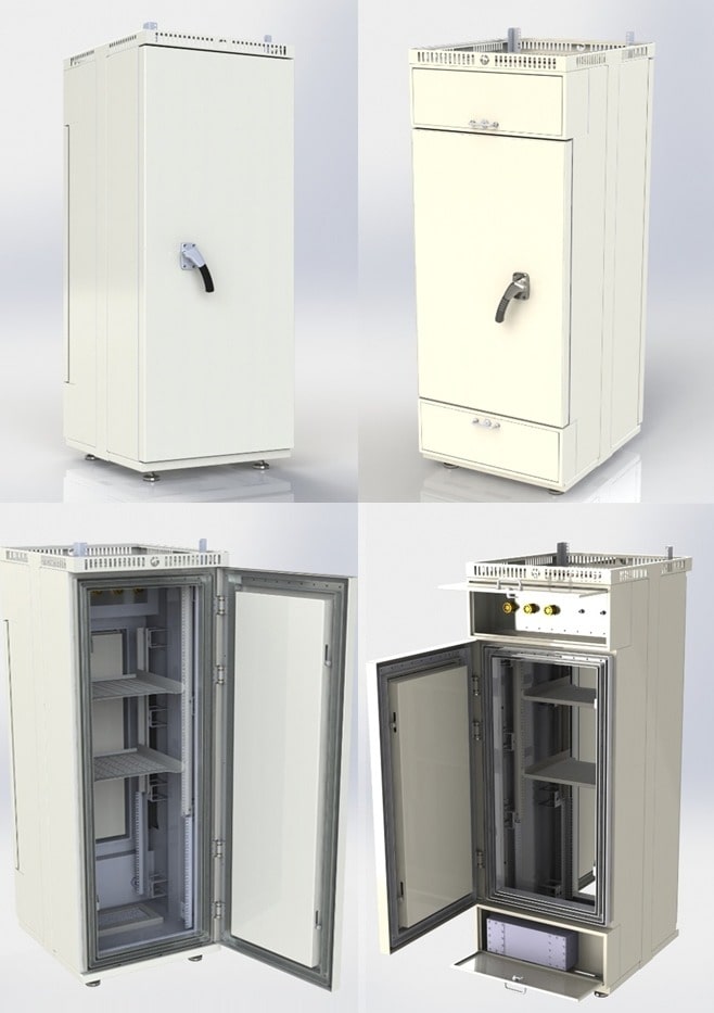
The EMP Protection Shielded Rack offers a highly effective, space-saving, and cost-efficient defense solution for mission-critical network equipment, serving commercial, government, and defense sectors. This system provides superior protection compared to full EMP facility coverage, with a shorter lead time.
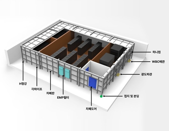
The EMP Protection Facility is a comprehensive solution designed to safeguard critical infrastructure against Electromagnetic Pulse threats, built in compliance with the MIL-STD-188-125-1 standard.
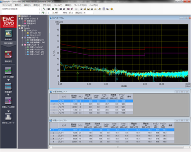
No1 Quality EMC Measurement Software TOYO Corporation has designed and developed EMC measurement software for more than 35 years. Throughout the world, more than 1000 TOYO systems have been chosen by governmental communications regulating agencies and many major companies, such as Competent Body,to form the core and standard of their test and evaluation installations. Supporting a wide range of needs, from design improvement to final qualification test, TOYO continues as the world’s first choice in integrated EMC test systems and software because TOYO places exceptional importance on user feedback.

ES10VE for Vehicles measurement has been added to ES10 series of TOYO next-generation EMC measurement software. ES10/VE supports latest edition of CISPR 25 Edition 4 Annex I (Evaluation of power supply systems for high-voltage components to be used on EV/HV) This software also supports MIL RE, CE mesasurement.
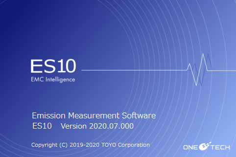
TOYO has developed and sold a number of EMI measurement software applications to respond to various customer needs. The software roughly falls under two main series – the “EP5” and ”EP7” series that has established its position as the industry standard, supporting various EMI receiver models and EMI measurement equipment and the high-end “EPX” series that fully utilizes the features of Keysight Technologies top-of-the-line EMI receiver “N9048B PXE”. With the “ES10” developed on the same platform (fundamental software structure) as the “EPX” the functional differences among the series have been minimized or eliminated, and the new features will be delivered to the user in a shorter time. ES10″ replaces the existing “EP5” and “EP7”, and “EPX” and “ES10” are the two pillars of TOYO’s EMI measurement software.

The “EPX/VE” is a software product that measures and analyzes the electromagnetic noise emitted from automobile and on-vehicle equipment. Combined with Keysight’s EMI receiver, “N9048B PXE,” this software helps prevent you from missing any noise and identify the part that emits noise along with the location of the noise source. By making it easier to pinpoint the noise source, development engineers are now able to take countermeasures against such noise at each step of the development cycle more efficiently, which leads to the reduction in overall development time.

Eretec Inc. provides TOYO's latest software portfolio to meet customers' diverse EMI measurement and analysis needs. EMINT is a high-performance analysis software that supports EMI (Electromagnetic Interference) reduction countermeasures based on AI and Digital Technology. This software offers automated analysis functions through its AI engine, including identifying key component sources of EMI noise, searching for countermeasures based on similar case studies, and providing relevant technical documentation. Furthermore, it is designed to utilize Digital Transformation (DX) technologies to allow for real-time sharing and systematic management of measurement data.
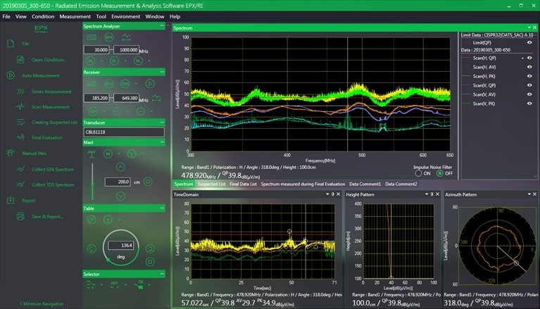
Latest EMC measurement software “EPX/RE” leading the Accelerated Time Domain Scan feature a success The “EPX/RE”, completely new radiated emission measurement and evaluation software enables highly reliable EMI measurement without missing any noise, which is achieved by embedding in its auto measurement sequence the Accelerated Time Domain Scan feature, an optional feature for Keysight Technologies’ N9048B PXE EMI receiver. The measured noise data are also quite effective for taking countermeasures against noise as you can analyze the behavior of noise in relation to frequency but also in time sequence.
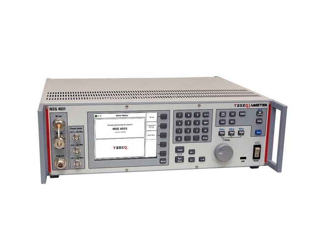
The broadband immunity test system NSG 4031 has been designed for testing in accordance with IEC / EN 61000-4-31. It contains a white noise generator with four different band filters to allow band limited testing as may be required in future product standards. The internal power meter are capable to show the forward power as well as the VSWR of the connected setup. The three front panel inputs allow an easy test level setting procedure. The internal power amplifier with more than 80 Watts output power allows test levels 1 to 3 as given in table 1 of IEC / EN 61000-4-31 also including an optional 2 dB attenuator which can be used in case of severe EUT mismatch. Due to the powerful and easy to use firmware, the NSG 4031 is independent from an external PC and control software.
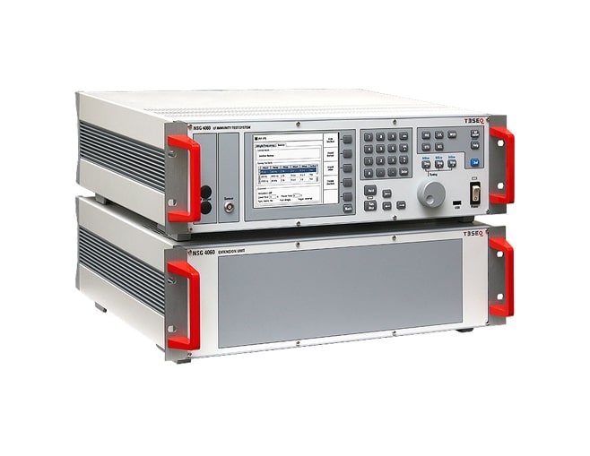
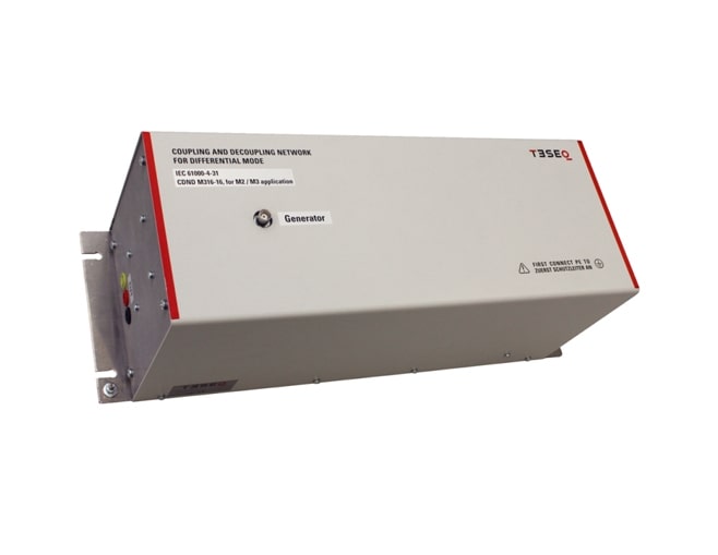
The NSG 4060 is an EMC immunity test system for the frequency range 15 Hz to 150 kHz. It consists of a sine wave generator, power amplifier, EUT monitoring interfaces and different coupling units depending on the application, i. e. NSG 4060-1 for testing IEC / EN 61000-4-16 including short duration disturbance tests for DC, AC from 162/3 Hz to 200 Hz and test levels up to 300 V. Voltage testing according IEC / EN 61000-4-19 requires the combination with CDND M316-2. It includes the differential mode coupling and decoupling and the required 10 Ω impedance of the disturbance source. Current testing according IEC / EN 61000-4-19, e.g. testing electricity meters, requires the combination with CT 419-5. The powerful and easy to use firmware makes the NSG 4060 independent from an external PC and control software, however it can also be remote controlled for system operation. Part of NSG 4060’s delivery is an USB-to-serial / optical converter which offers potential free remote control.
The NSG 4070C-LFCP is a universal device for standard-compliant and development-accompanying EMC immunity tests in the application area of magnetic field testing in the close proximity according to IEC / EN 61000-4-39 and IEC / EN 60601-1-2. The NSG 4070C-LFCP integrates signal generator, directional coupler, power amplifier, power meter and EUT monitoring interfaces. The NSG 4070C-LFCP can be operated quickly, conveniently and easily via the front panel as a free-standing device. Test and measurement data can be conveniently transferred for documentation purposes via a USB stick. The NSG 4070C-LFCP can be remote controlled via LAN, electrical or optical RS232 as well as USB. The wide frequency range of the signal generator and the power meter offer the possibility to connect external amplifiers and directional couplers. In combination with a remote control software, external power amplifiers and directional couplers, further applications can be covered, such as testing of conducted disturbances induced by high frequency fields according to IEC / EN 61000-4-6, automotive BCI tests e.g. according to ISO 11452-4 as well as high frequency electromagnetic fields according to IEC / EN 61000-4-3 or IEC / EN 61000-4-20. For EUT monitoring, the NSG 4070C-LFCP offers a variety of interfaces for flexibility in laboratory use. In order to start with predefined parameter settings the optional test software icd.control is recommended. The software offers a large standard database and predefined drives for using external measuring devices. More complex systems including radiated tests can be controlled by using the software solution CIS (Compliance Immunity Software).
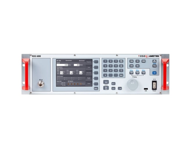
The NSG 6000 consists of an integrated RF signal generator, RF switch and EUT monitoring interfaces. The unit is designed for various EMC applications in the 9 kHz to 6 GHz frequency range. In addition to the generator, the system includes the AM and PM modulators necessary for EMC testing. The NSG 6000 includes 3 freely configurable pulse modulators (1 μs to 200 s) for radar pulse profiles as required e.g. by Ford FMC1278 or VW TL81000. The RF signal can be switched to one of five outputs, where up to five power amplifiers can be connected directly. Different RF switches are supplied for combining amplifiers into two antenna paths or other applications.
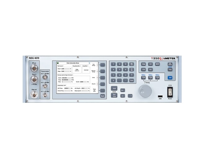
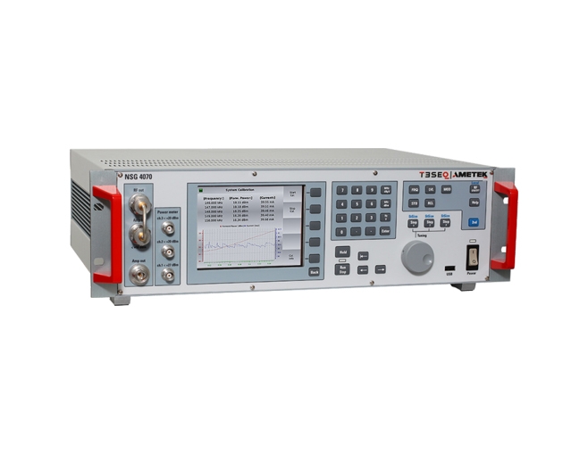
The NSG 4070 is a multi-functional device for carrying out EMC immunity tests to accompany development and conformity testing in accordance to IEC / EN 61000-4-6, Namur and several automotive BCI standards. Anyone who spends a considerable amount of time on test level setting, connecting EUT monitoring or writing test reports can now carry out immunity testing in a much more efficient manner with the 5th generation of NSG 4070. Its modular set-up using internal or external amplifiers enables a large variety of applications. The powerful and easy to use firmware makes the NSG 4070 independent from an external PC and control software, however it can also be remote controlled for system operation. A state-of-the-art data transfer of test and measurement data for documentation is provided by USB stick to be plugged into the front panel.
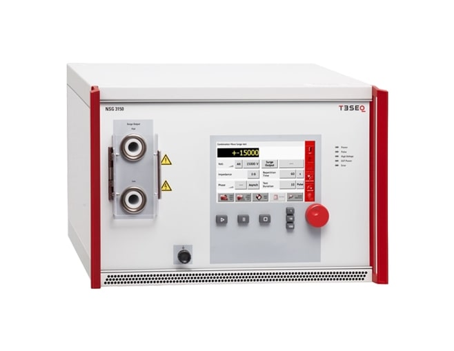
TESEQ’s new NSG 3150 15 kV Combination Wave Surge generator sets a new standard in the industry and represents the perfect solution for your immunity tests in compliance with IEC/EN 61000-4-5. Unique NSG 3150 capabilities enable users not only to perform tests according to exact standard requirements, but also to go beyond. The flexible repetition time setting which enables a significant reduction of test times is only one of many examples. The perfect solution for testing outdoor applications, the new NSG 3150 is used to test lighting, communication and energy distribution equipment, railways and protection systems and relays (e.g. IEC 60255-26). The 15kV surge pulse voltage allows manufactures to reach new quality levels, which helps them to outperform competitors.

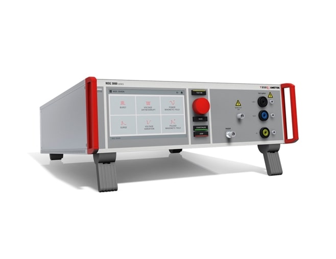
Teseq’s new NSG 3060A conducted immunity generator takes the proven, user-friendly design of the highly successful NSG 3000 series to a new level. This innovative design uses modular architecture to provide a versatile system that can be configured for basic testing needs and expanded to meet the needs of sophisticated test laboratories. Designed to fulfill requirements for CE mark and ANSI C62.41 testing, the NSG 3060A performs tests for Combination wave surge, Ring wave and Electrical Fast Transient (EFT) pulses as well as Power Quality Testing (PQT). Extensive expansion capabilities enable the system to be configured for a much broader range of applications. Using state of the art components, the self-contained modules set new standards with respect to switching and phase accuracy and exceed the existing standards’ requirements. With its powerful processors, the NSG 3060A can completely fulfill the unique coupling requirements specified by ANSI C62.41. This standard requires that the pulse amplitude be adjusted for the phase position of the pulse on the AC mains, and for the amplitude of the mains voltage. A 7” touch panel display with superb contrast and color is the most striking feature of the new NSG 3060A. For fast and efficient data entry, input devices include an integrated keyboard and a thumbwheel with additional keys for sensitivity adjustment. The user-friendly graphic display speeds test setup. Each parameter’s value is highly visible, and all settings can be quickly selected and modified with the generously sized touch input buttons. A stylus is not necessary, and ramp functions are programmed quickly and easily. Multi-step test procedures can be created and their sequence or parameter values changed easily. The users can make manual parameter changes using the thumbwheel while a test is under way, providing an effective and fast method for identifying critical threshold values. The Test Assistance (TA) function allows users to initiate standardized test with just a few “clicks” to achieve quick, reliable results in a development environment. The NSG 3060A has an Ethernet port for external PC control. The Windows-based control software simplifyes test programming and allows compilation of complex test sequences with diverse pulse types. Test reports can be generated during the test operation, allowing the operator to enter observations as the test progresses and increasing the efficiency of long-term tests.
Teseq’s new NSG 3040A is an easy-to-use multifunction generator that simulates electromagnetic interference effects for immunity testing in conformity with international, national and manufacturers’ standards including the latest IEC/EN standards. The NSG 3040A system is designed to fulfill conducted EMC test requirements for CE mark testing, which generally include combination wave surge, Electrical Fast Transient (EFT) pulses and Power Quality Testing (PQT). Extensive expansion capabilities enable the system to be configured for a much broader range of applications. Featuring an innovative, modular design, the NSG 3040A is a versatile system that can be configured for basic testing needs and expanded to meet the needs of sophisticated test laboratories. Using state-of-the-art components, the self-contained modules set new standards with respect to switching and phase accuracy and exceed the existing standards’ requirements. A 7” touch panel display with superb contrast and color makes controlling the NSG 3040A easy. For fast and efficient data entry, input devices include an integrated keyboard and a thumbwheel with additional keys for sensitivity adjustment. To achieve quick, reliable results in a development environment a standardized test can be initiated with just a few “clicks” using the integrated Test Assistance (TA) function. Convenient touch input buttons make each parameter’s value highly visible and allow the user to quickly select and modify all settings. A stylus is not necessary, and ramp functions can be programmed quickly and easily. Multi-step test procedures can be created and their sequence or parameter values can be changed easily. With expert mode users can make manual parameter changes using the thumbwheel while a test is under way, providing an effective and fast method for identifying critical threshold values. The NSG 3040A has an Ethernet port for external PC control. The Windows-based control software simplifies test programming and compilation of complex test sequences with various types of tests. Test reports can be generated during the test operation, allowing the operator to enter observations as the test progresses and increasing the efficiency of long-term tests.
The AES 5501 is a system of electronic and mechanical switches, an artificial network, and a unique control station designed for emissions testing to ISO 7637-2. Having gone through meticulous development and intensive beta testing, the AES 5501 contains unique features and uncompromising quality and conformity found nowhere else. Consisting of a four-part solution, the user has complete control over where, when and how the switches can be placed and controlled, including the necessary drive voltages for the relays.
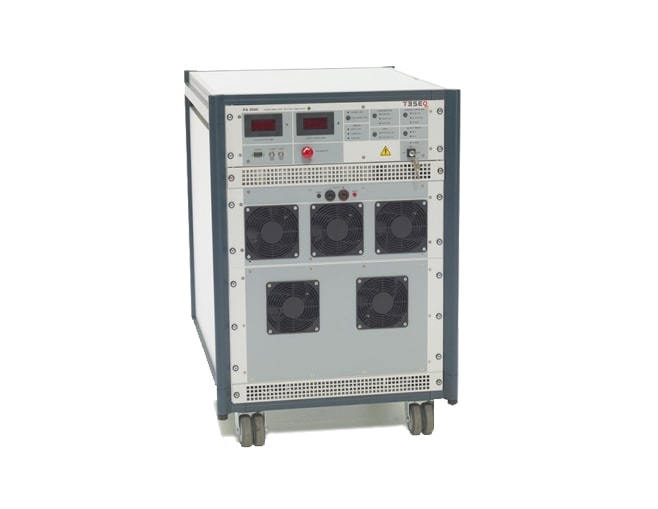
This battery simulator is designed to replace the vehicle battery in the test environment. These sources must fulfill various criteria concerning power rating, voltage, slew rate, impedance, etc. depending on the particular application. Bi-polar current sources are specified for in several cases. With bandwidths three times the other amplifiers and inrush currents far exceeding other comparable solutions, pulse 2b, pulse 4, sine wave noise and other complex simulations are realm of the PA 5840 series. Of course the amplifier is also perfectly suited for ISO 7637 compliant simulated conducted transient testing. Offering combinations of features that exist in no other battery simulator, the PA 5840 series is the right product for your EMC needs. Designed specifically for automotive EMC testing, Teseq’s 42V ready amplifier sets the pace for automotive battery simulation including features necessary for automotive immunity testing such as sense wires for cable voltage drop compensation and several operating modes for stability with complex automotive loads. Consistent with the philosophy of the Teseq’s EMC concept, the PA 5840 utilizes a modular structure so that upgrades can be implemented in the future. The control unit, power stage and power supply are all separate rack-mounted functional units for easy exchanges and upgrading.
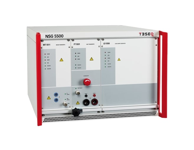
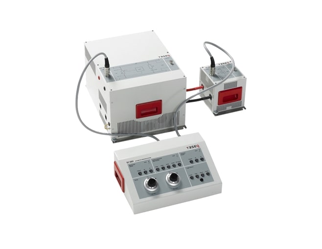
The compact and modular NSG 5500 solution offers the generators necessary for tests with capacitive discharge pulsed interference as called for by ISO, SAE, DIN and JASO, and others. The established test specifications for passenger cars together with the new standards for commercial vehicles published by these international and other bodies are fully covered, as are the most company-specific standards from vehicle manufacturers. Based on our exclusive Gemini technology, Teseq offers the most flexible and upgradeable system to protect the users’ investment. NSG 5500 system. This compact mainframe houses the common system components and accommodates the standard pulse generators. All testing is available from one output connector. An electronic switch to connect and disconnect the battery supply is in-corporated in the NSG 5500. Additional inputs and outputs are located on the rear panel for test execution control purposes and the monitoring of error signals, oscilloscope triggers, gate start/stop commands, etc. Overall control is via a PC running AutoStar™ under Windows.
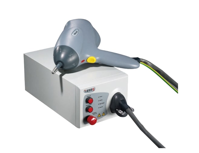
Ergonomic design and advanced functionality. The NSG 438 ESD simulator is designed to sit comfortably in the operator’s hand, with operating conditions constantly displayed and accessible on a bright, clear color touch display. NSG 438 comprehensively fulfills virtually all international standard requirements. Based on over 60 optional discharge networks, the NSG 438 can meet any of today’s automotive manufacturers’ standards. The simulator is simple, convenient and safe to use. The whole range of parameter settings including polarity selection, freely adjustable pulse repetition, counter functions and discharge detection is available up to the maximum discharge voltage. The color touch display and keypad for parameter input shows the precise functional and test data with user-selectable language for convenient and safe operation worldwide. The simulator contains variable threshold selection for accurate discharge detection. This detection feature can be switched off when testing EUT’s with non-conductive surfaces, such as plastic housings. Pre-programmed settings for IEC 61000-4-2 and ISO 10605 ensure that the simulator is automatically set up correctly and the appropriate discharge network is installed. The actual RC value is displayed at all times. Molded HV discharge networks in solid cases eliminate ionization and leakage current effects. Precisely tuned combinations of RC components guarantee wave shape parameters to be within tolerances. A unique activity log is included so that the types and numbers of ESD simulations can be easily scrolled through to check what has been tested and in what timeframe.

Ergonomic design and advanced functionality. The NSG 437 ESD simulator is designed to sit comfortably in the operator’s hand, with operating conditions constantly displayed and accessible on a bright, clear color touch display. NSG 437 comprehensively fulfills virtually all international standard requirements. Based on over 60 optional discharge networks, the NSG 437 can meet any of today’s automotive manufacturers’ standards. The simulator is simple, convenient and safe to use. The whole range of parameter settings including polarity selection, freely adjustable pulse repetition, counter functions and discharge detection is available up to the maximum discharge voltage. The color touch display and keypad for parameter input shows the precise functional and test data with user-selectable language for convenient and safe operation worldwide. The simulator contains variable threshold selection for accurate discharge detection. This detection feature can be switched off when testing EUT’s with non-conductive surfaces, such as plastic housings. Pre-programmed settings for IEC 61000-4-2 and ISO 10605 ensure that the simulator is automatically set up correctly and the appropriate discharge network is installed. The actual RC value is displayed at all times. Molded HV discharge networks in solid cases eliminate ionization and leakage current effects. Precisely tuned combinations of RC components guarantee wave shape parameters to be within tolerances. A unique activity log is included so that the types and numbers of ESD simulations can be easily scrolled through to check what has been tested and in what timeframe.
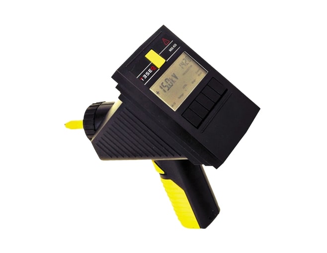
Ergonomic design and advanced functionality. The pistol-shaped NSG 435 simulator is designed to sit comfortably in the operator’s hand, with current operating conditions constantly displayed and clearly visible. NSG 435’s microprocessor-based controller and multifunction keypad provide the operator with instant access to its comprehensive range of built-in functions. The LCD panel continuously displays the operating status and all user-selected test parameters. NSG 435 has its own internal, battery operated high voltage generator. In addition to the pre-programmed, standard IEC pulses, the user can create custom tests using single or repetitive discharges with selectable rates and manual or automatic polarity switching. An optional mains supply is available for extended test operation or for use when the battery is being charged.
The active loop antenna HLA 6121 is designed for operation in the frequency range 9 kHz to 30 MHz. It is ideally suited for magnetic field measurements as required by several standards (e.g. CISPR 11, CISPR 16-1-4, CISPR 16-2-3, FCC 18 and others). The built-in preamplifier matches the extremely low impedance of the loop to the measuring receiver. The HLA 6121 has a constant factor over the whole of its frequency range, making it ideal for swept measurement systems. The antenna is powered by an external DC supply like the EMI receiver’s transducer supply, battery pack or with the included power supply unit PSU 6001. The delivery of the HLA 6121 includes an adapter which offers the DC supply of the HLA 6121 via the coaxial cable. It allows most flexible operation and the location of the power supply unit outside the chamber.
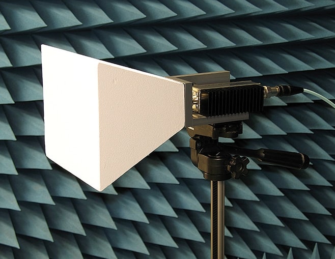
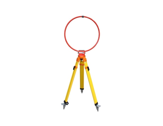
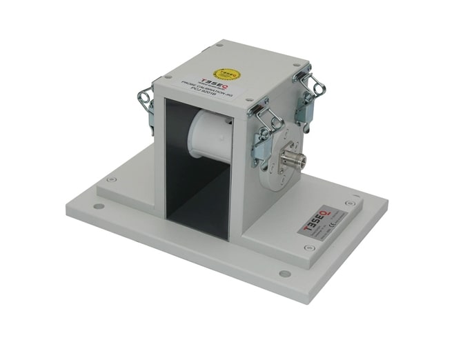
The basic EMC publication IEC / EN 61000-4-39 „Electromagnetic Compatibility (EMC) - Part 4-39: Testing and measurement techniques - Radiated fields in close proximity - Immunity test” describes test methods unique to the situation in which the transmitter is used in close proximity to the EUT. The Teseq TEM horn generates homogeneous fields in the large frequency range from 600 MHz to 6 GHz. Two optional available matching network adapters allow to extend the frequency range for the TETRA 400 and GMRS 460 / FRS 460 applications. Using the adapters means one TEM horn for all the bands. The mounting fixture allows easy adjustment for vertical, horizontal polarizations, and has a standard camera thread (1/4” X 20) hole that allows fitting to many support structures including all Teseq tripods (note Teseq adapters may be required). The combination TEM horn with dipole tube BAA 6001 is recommended for mounting the TEM horn to ∅ 22 mm mast / tripod holder.
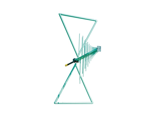
Three Antennas In One The CBL 6112 operates over the unprecedented, wide range 30 MHz to 2 GHz. It effectively combines the performance of three standard EMC antennas, the Biconical, the Log Periodic and the Waveguide Horn. Considerable savings in the order of 40 - 50% can be made in expensive test time, plus the added benefit of improved repeatability and reliability by not having to laboriously disconnect and reconnect antennas during testing.
The ‘Classic’ BiLog® Antenna The CBL 6111 is a high performance ultra wideband BiLog® antenna for emission and immunity EMC testing. This is the original ‘classic’ BiLog® combining two antennas in one, making savings of at least 20 - 30% on test time and reducing measurement errors due to cable and connector wear.
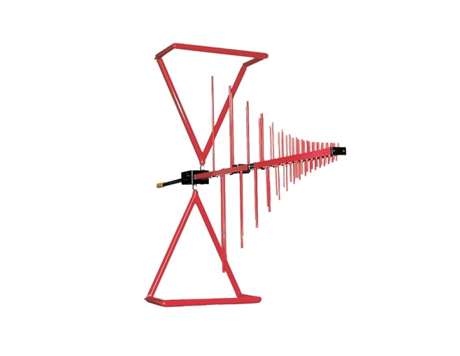
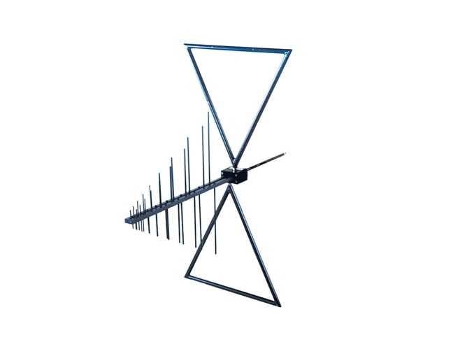
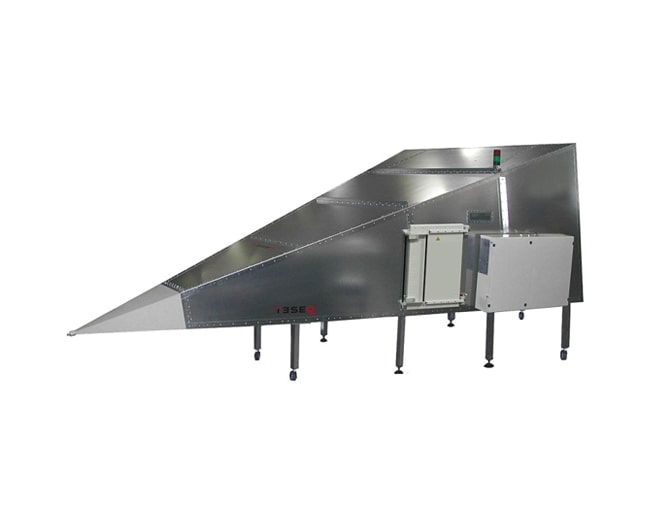
The Compact X-Wing® BiLog® for RF EMC immunity testing The combination of BiLog® technology with novel low frequency, folded elements (X-Wings®) allows low frequency power to be efficiently projected forward without significantly affecting the high frequency performance and, at the same time, reduces the chamber coupling effects. The CBL 6143 has a unique matching network which will allow powers of up to 300 Watts CW to be transmitted, making it suitable for most immunity measurements requiring fields of 10 V/m, or even greater.
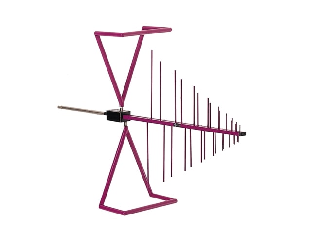
The Compact X-Wing® BiLog® For RF EMC emission and immunity testing in compact anechoic chambers. The combination of BiLog® technology with novel low frequency, folded elements (X-Wing®) allows low frequency power to be efficiently projected forward at 80 MHz without significantly affecting the high frequency elements.
A high power density, design has allowed us to produce a dual-band series with power levels from 30 to 50 watts P1dB, 20 MHz to 6 GHz solid-state amplifier in either a compact 4U or 7U package. This amplifier series is not only ideal for RF immunity testing to standards such as ISO11452-9 but also many 5G infostructure component tests. The touch screen colour display gives an immediate visual indication of the operating status of the amplifier and access to diagnostic information such as gate current and heatsink temperature. The fan speed adjusts depending on the heatsink temperature thus ensuring the minimum audio noise level possible in the operating environment. The dual directional calibrated coupler provides a quick and easy way to monitor forward and reflected power with any power meter. Input overdrive protection prevents damage to the input devices due to accidental high input power. Multiple remote interfaces are available as standard including USB, GPIB, RS232, and Ethernet. Amplifier gain can be controlled either remotely through one of the available interfaces or via the front panel touch screen.
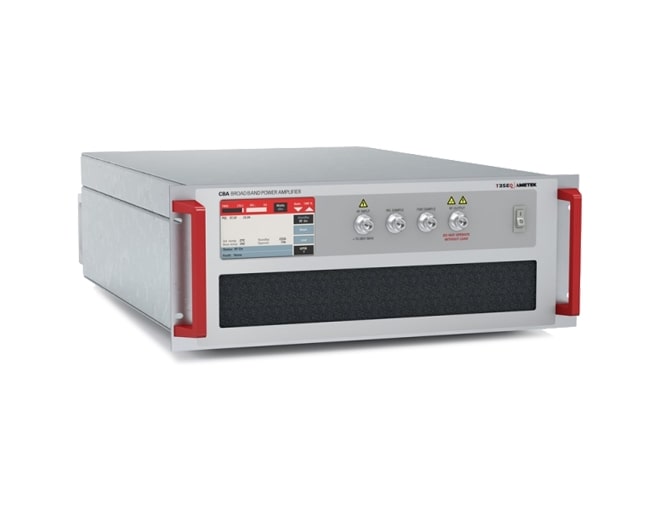
Class A, high power density, design has allowed us to produce a 0.8 GHz to 4 GHz amplifier series with power levels from 30 to 800 watts P1dB. These amplifiers are ideal for RF immunity testing in a GTEM Cell or with a wide range of available horn antenna such as the Teseq BHA range or readily integrated with an NSG 6000 to form part of a broadband RF test system. The touch screen colour display gives an immediate visual indication of forward and reverse power along with the current operating status of the amplifier and access to diagnostic information such as gate current and heatsink temperature. Fan speed adjusts depending on the heatsink temperature thus ensuring the minimum audio noise level possible in the operating environment. The inbuilt calibrated forward power coupler provides a quick and easy way to monitor forward power with any power meter. Input overdrive protection prevents damage to the input devices due to accidental high input power. Multiple remote interfaces are available as standard including USB, GPIB, RS232, and Ethernet.

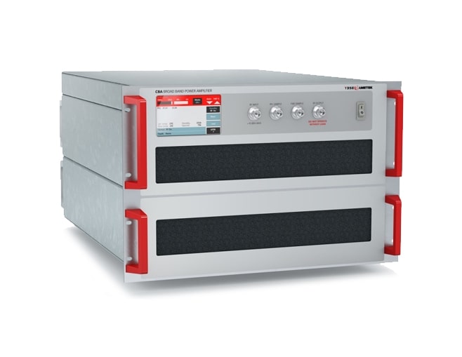
A high-power density, design has allowed us to produce a 0.8 GHz to 6.0 GHz amplifier in a compact 20U Rack. With a minimum of 400/300 watts of linear power CW and 900/600 watts of saturated CW power over the frequency ranges of 1.2-1.4 GHz and 2.7-3.2 GHz. This amplifier is ideal for RF immunity testing and coupled with a wide range of available horn antenna makes this amplifier particularly suited for Radar Automotive Pulse Testing and can also be integrated with the Teseq NSG 6000 to form part of a broadband test system. The touch screen color display gives an immediate visual indication of forward and reverse power along with the current operating status of the amplifier and access to diagnostic information such as gate current and heatsink temperature. Fan speed adjusts depending on heatsink temperature thus ensuring the minimum audio noise level possible in the operating environment.The inbuilt calibrated forward power coupler provides a quick and easy way to monitor forward power with any power meter. Multiple remote interfaces are available as standard including USB, GPIB, RS232, Ethernet.
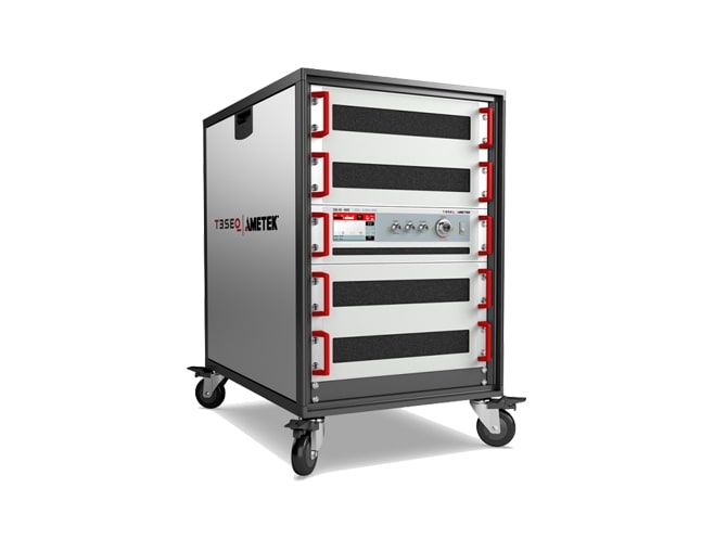
A high-power density, design has allowed us to produce a 0.8 GHz to 4.0 GHz amplifier in a compact 20U Rack. With a minimum of 400 watts of linear power CW and 900/600 watts of saturated CW power over the frequency ranges of 1.2-1.4 GHz and 2.7-3.5 GHz. This amplifier is ideal for RF immunity testing and coupled with a wide range of available horn antenna makes this amplifier particularly suited for Radar Automotive Pulse Testing and can also be integrated with the Teseq NSG 6000 to form part of a broadband test system. The touch screen color display gives an immediate visual indication of forward and reverse power along with the current operating status of the amplifier and access to diagnostic information such as gate current and heatsink temperature. Fan speed adjusts depending on heatsink temperature thus ensuring the minimum audio noise level possible in the operating environment.The inbuilt calibrated forward power coupler provides a quick and easy way to monitor forward power with any power meter. Multiple remote interfaces are available as standard including USB, GPIB, RS232, Ethernet.

Class A, high power density, design has allowed us to produce a 1.0 GHz to 6 GHz amplifier series with power levels from 30 to 400 watts P1dB. These amplifiers are ideal for RF immunity testing in a GTEM Cell or with a wide range of available horn antenna such as the Teseq BHA range or readily integrated with an NSG 6000 to form part of a broadband RF test system. The touch screen colour display gives an immediate visual indication of forward and reverse power along with the current operating status of the amplifier and access to diagnostic information such as gate current and heatsink temperature. Fan speed adjusts depending on the heatsink temperature thus ensuring the minimum audio noise level possible in the operating environment. The inbuilt calibrated forward power coupler provides a quick and easy way to monitor forward power with any power meter. Input overdrive protection prevents damage to the input devices due to accidental high input power. Multiple remote interfaces are available as standard including USB, GPIB, RS232, and Ethernet.
This low frequency amplifier series can be used in conjunction with other amplifiers from the Teseq range to cover the entire frequency range from 10 kHz to 40 GHz with convenient frequency break points allowing you to optimise the power level in each range. The Class A design ensures a high reliability, low distortion linear performance across the frequency range. This design also ensures that the amplifier series will continue to operate at full power even when presented with an open or short circuit at its output. The units are powered from a switched mode power supply for high efficiency, high power factor and wide voltage range operation. Air-cooled with integral fans, and are protected against faulty cooling by excess temperature sensing. A safety interlock connector is provided, which the user can short circuit to ground, to put the amplifiers into standby mode. Front panel indicators are provided to indicate over-temperature and rf interlock operation.

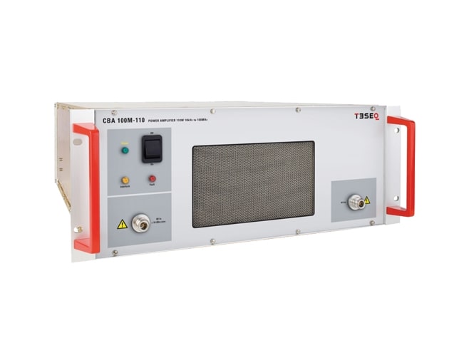
Designed specifically for conducted EMC testing, this mismatch tolerant Class A amplifier series is ideally suited to provide power into a CDN for IEC 61000-4-6 conducted susceptibility testing up to and beyond the normal 10 V emf test level. The Class A design ensures a high reliability, low distortion linear performance across the frequency range. This design also ensures that the amplifiers will continue to operate at full power even when presented with an open or short circuit at its output. The units are powered from a switched mode power supply for high efficiency, high power factor and wide voltage range operation. Aiir-cooled with integral fans, and are protected against faulty cooling by excess temperature sensing. Front panel indicators are provided to indicate over-temperature.
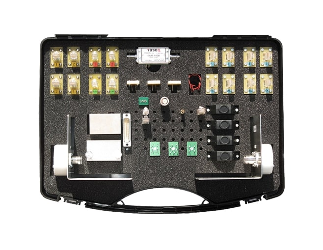
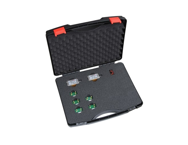
The calibration kit CAS ISN is made for function tests and remeasurements on impedance stabilization network (ISN) for unshielded balanced pairs. Measuring parameters are common mode (CM) impedance, phase angle, voltage division factor, decoupling attenuation (isolation) and longitudinal conversion loss (LCL). Impedance stabilization networks (ISN) are defined in CISPR 22 and CISPR 16-1-2. The CISPR 16-1-2 gives additional requirements and provides examples and measurements for the networks. The ITU-T recommendations G.117 and O.9 offers the background knowledge for measurements on symmetrical telecommunication lines.
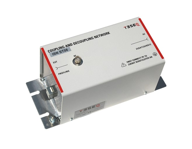
Impedance stabilization networks (ISN, or with CISPR 16-1-2 called AAN: asymmetric artificial network or AN: artificial networks for coaxial and other screened cables) are defined for measuring of conducted common mode disturbances at information technology equipment (ITE) as required in CISPR 22. The ISN is placed between the equipment under test (EUT) and auxiliary equipment (AE) or load which are necessary for the operation of the EUT. The ISN establishes the common-mode termination impedance for the EUT’s telecommunications port during measurement. All internal parts fulfill the requirements of cat.6 or better and provide optimal transfer performance. The used internal cable has a symmetrical impedance of 100 Ω. The pin- arrangement of the RJ45 sockets meets the requirements of EIA / TIA 568B. ISN ST08 meets the requirements of CISPR 22, EN 55022, CISPR 32, EN 55032, CISPR 16-1-2 and EN 55016-1-2. Unlike the ISN T types for unscreened balanced lines the ISN ST08 needs no additional adapters for LCL setting.
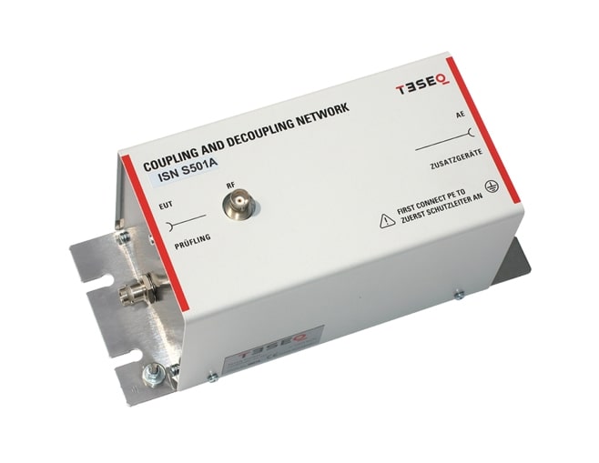
Impedance stabilization networks (ISN, or with CISPR 16-1-2 called AAN: asymmetric artificial network or AN: artificial networks for coaxial and other screened cables) are defined for measuring of conducted common mode disturbances at information technology equipment (ITE) as required in CISPR 22. The ISN is placed between the equipment under test (EUT) and auxiliary equipment (AE) or load which are necessary for the operation of the EUT. The ISN establishes the common-mode termination impedance for the EUT’s telecommunications port during measurement. ISN S501A, ISN S502A, ISN S751 and ISN S752 are designed for measurements on coaxial telecommunication lines. The used internal cable has a impedance of 50 Ω for ISN S501A and ISN S502A or 75 Ω for ISN S751 and ISN S752. The cable screen is connected on the AE side to the ground. ISN S502A and ISN S752 are supplied with double screened coaxial cables and N connector. A design example is given in figure D.9 CISPR 22 (EN 55022) and figure G.9 CISPR 32 (EN 55032).
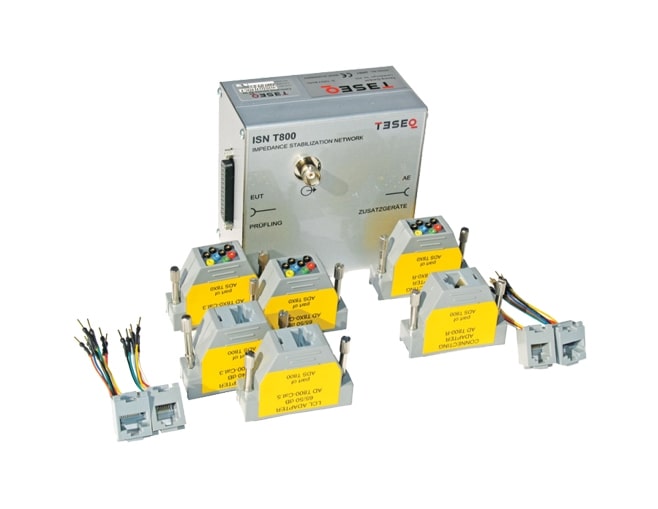
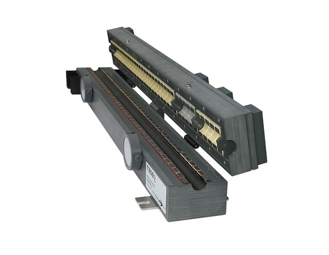
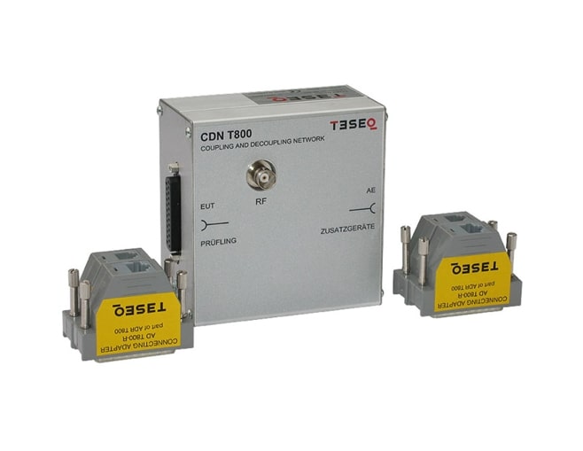
Impedance stabilization networks (ISN, or with CISPR 16-1-2 called AAN: asymmetric artificial network) are defined for measuring of conducted common mode disturbances at information technology equipment (ITE) as required in CISPR 22 and CISPR 32. The ISN is placed between the equipment under test (EUT) and auxiliary equipment (AE) or load which are necessary for the operation of the EUT. The ISN establishes the common-mode termination impedance for the EUT’s telecommunications port during measurement and emulates the unsymmetrical contribution (longitudinal conversion loss, LCL) of the connected line. Different ISNs are available in relation to the line category, line numbers and pin-arrangement. The ISN T8 is designed for measurements on up to four unscreened single balanced pairs and consists of one basic network (ISN T800) with D sub 25 connectors and special adapter sets. A set of adapters consists of two pieces of LCL adapters to arrange the lines and realize longitudinal conversion loss (LCL)- requirements for the EUT-side in relation to the use cable category (cat. 3, cat. 5) and one piece of connection adapter arranges the lines for the AE-side. Teseq offers two different adapter sets – ADS T800 and ADS T8x0. ADS T800 gives the connection to RJ45 sockets with pin-arrangements of EIA/TIA T568A respectively T568B. The adapter set ADS T8x0 offers changeable pin-arrangements via 1 mm banana connectors for each pin combination of RJ11/RJ45. The ISN T8 is designed for measurements on up to four unscreened single balanced pairs and consists of one basic network (ISN T800) with D sub 25 connectors and special adapter sets. A set of adapters consists of two pieces of LCL adapters to arrange the lines and realize longitudinal conversion loss (LCL)- requirements for the EUT-side in relation to the use cable category (cat. 3, cat. 5) and one piece of connection adapter arranges the lines for the AE-side. Teseq offers two different adapter sets – ADS T800 and ADS T8x0. ADS T800 gives the connection to RJ45 sockets with pin-arrangements of EIA/TIA T568A respectively T568B. The adapter set ADS T8x0 offers changeable pin-arrangements via 1 mm banana connectors for each pin combination of RJ11/RJ45.
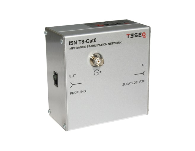
Impedance stabilization networks (ISN, or with CISPR 16-1-2 called AAN: asymmetric artificial network) are defined for measuring of conducted common mode disturbances at information technology equipment (ITE) as required in CISPR 22 and CISPR 32. The ISN is placed between the equipment under test (EUT) and auxiliary equipment (AE) or load which are necessary for the operation of the EUT. The ISN establishes the common-mode termination impedance for the EUT’s telecommunications port during measurement and emulates the unsymmetrical contribution (longitudinal conversion loss, LCL) of the connected line. Different ISNs are available in relation to the line category, line numbers and pin-arrangement. The ISN T8-Cat6 is designed for measurements on up to four unscreened single balanced pairs with cable category cat. 6. It can also be used as CDN for immunity testing according IEC/EN 61000-4-6 up to 80 MHz. The ISN T8-Cat6 is designed for measurements on up to four unscreened single balanced pairs with cable category cat. 6. It can also be used as CDN for immunity testing according IEC/EN 61000-4-6 up to 80 MHz.
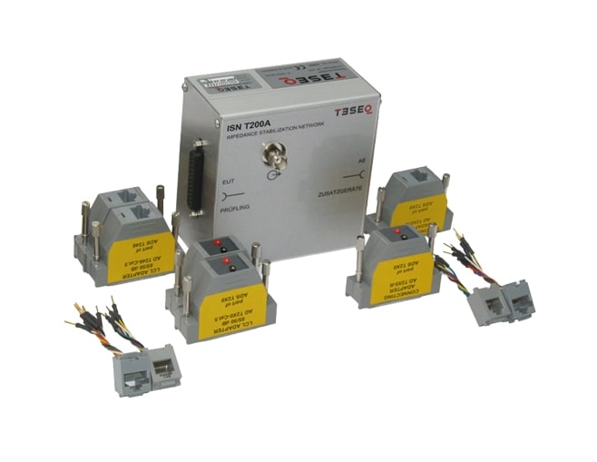
Impedance stabilization networks (ISN, or with CISPR 16-1-2 called AAN: asymmetric artificial network) are defined for measuring of conducted common mode disturbances at information technology equipment (ITE) as required in CISPR 22 and CISPR 32. The ISN is placed between the equipment under test (EUT) and auxiliary equipment (AE) or load which are necessary for the operation of the EUT. The ISN establishes the common-mode termination impedance for the EUT’s telecommunications port during measurement and emulates the unsymmetrical contribution (longitudinal conversion loss, LCL) of the connected line. Different ISNs are available in relation to the line category, line numbers and pin-arrangement. The ISN T2A is designed for measurements on one unscreened balanced pair and consists of one basic network (ISN T200A) with D sub 25 connectors and special adapter sets. A set of adapters consists of LCL adapters to realize the longitudinal conversion loss (LCL)- requirements for the EUT-side in relation to the used cable category (cat. 3, cat. 5) and a connection adapter for the AE-side.
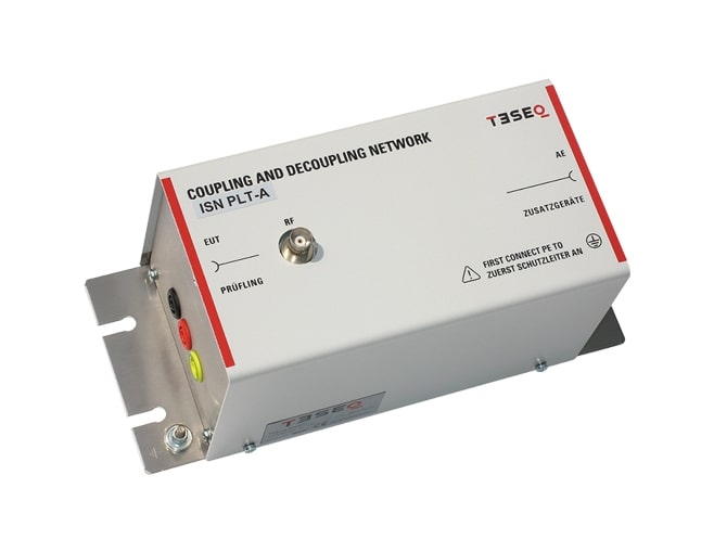
The ISN PLT-A is made for measurements on PLT devices which use one port for mains power supply and telecommunications (PLT port). It is conform with the requirements of EN 50561-1. Included in the delivery is the Coupling Unit (CU) as given in figure 3 of the standard.

The HV-AN 1u-500 ISO 21498 are artificial networks used for electric vehicle high voltage component tests up to 500 ADC. The AN simulates the impedance of a vehicle harness and battery and is used for emission measurements. It meets the requirements of ISO 21498-2, MBN 11123, BMW GS95023 and similar standards. The HV-AN 1u-ISO 21498 is based on a modular concept. Each module incorporates the 1 uH inductance, 1 uF capacitor and one resistance value. A pair of two HV-AN 1u-ISO21498 forms a complete set for HV+ and HV- supply lines to high voltage components. Separate sets are available for each resistance value and EUT current.
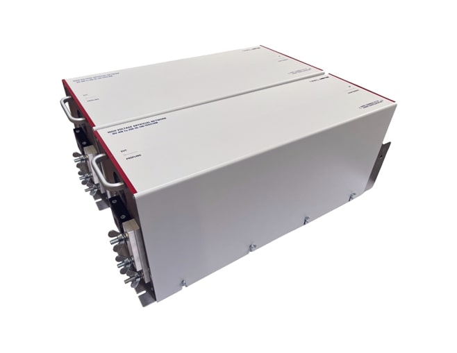
The HV-AN 1u-250 ISO 21498 are artificial networks used for electric vehicle high voltage component tests up to 250 ADC. The AN simulates the impedance of a vehicle harness and battery and is used for emission measurements. It meets the requirements of ISO 21498-2, MBN 11123, BMW GS95023 and similar standards. The HV-AN 1u-ISO 21498 is based on a modular concept. Each module incorporates the 1 uH inductance, 1 uF capacitor and one resistance value. A pair of two HV-AN 1u-ISO21498 forms a complete set for HV+ and HV- supply lines to high voltage components. Separate sets are available for each resistance value and EUT current.
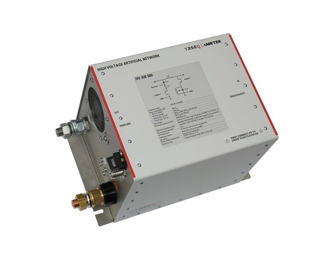
The artificial network HV-AN 500 offers a solution for high current and high voltage connections to the EUTs. The AN is used to simulate the impedance of a vehicle harness to determine the behavior of EUT and meet the requirements of ISO 7637-2 and the HV part of CISPR 12 (draft), CISPR 25, ECE No. 10 R05 / 06, ISO 11452-1 and ISO / DTS 7637-4. The optional available HV-AN 500-option-1μF, connected on the AE port of the HV-AN 500, allows testing of the LV part of CISPR 25, ECE No. 10 R06 and ISO 11452-1.
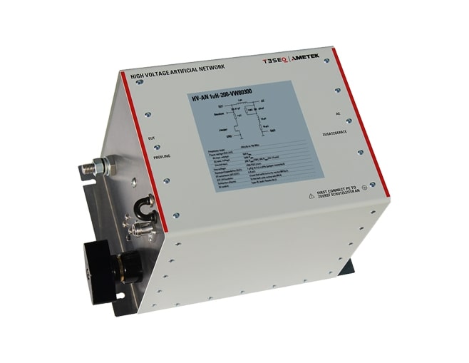
The artificial network HV-AN 1uH-200-VW80300 offers a solution for high current and high voltage connections to the EUTs as proposed in VW 80300. The AN is used to simulate the impedance of a vehicle harness to determine the behavior of EUT.
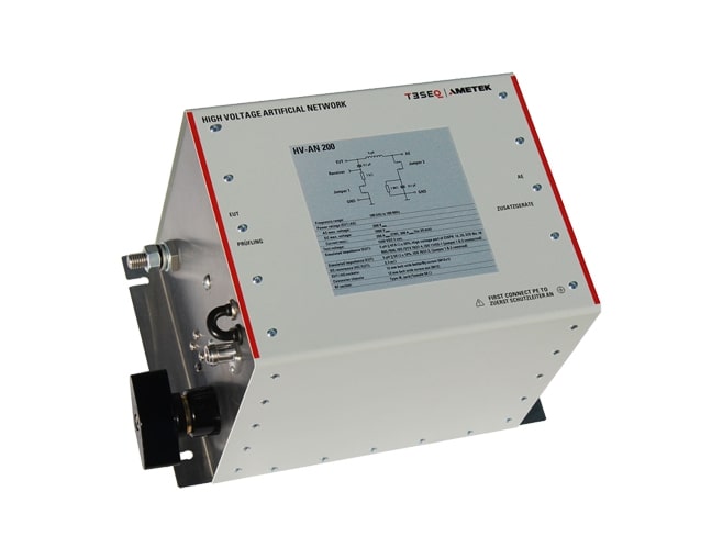
The artificial network HV-AN 200 offers a solution for high current and high voltage connections to the EUTs. The AN is used to simulate the impedance of a vehicle harness to determine the behavior of EUT and meet the requirements of ISO 7637-2 and the HV part of CISPR 12 (draft), CISPR 25, ECE No. 10 R05 / 06, ISO 11452-1 and ISO / DTS 7637-4.
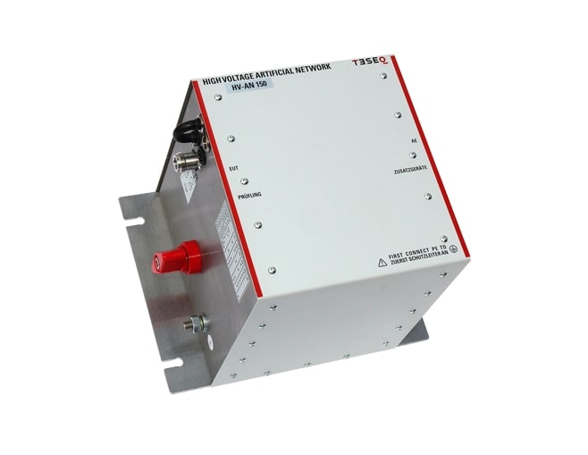
Teseq’s artificial network HV-AN 150 is the first universal solution which covers several applications and standards in the Automotive, Airborne and MIL range. It offers the right solution for both high current and high voltage EUTs and can be housed for having a shielded box, see option SME HV-AN 150, as proposed in CISPR 12 (draft), CISPR 25, ECE No. 10 R05 / 06, ISO 11452-1 and ISO / DTS 7637-4.
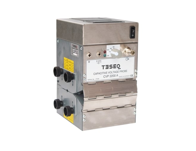
The CVP is used for measuring on telecommunication ports for lines with more than four balanced pairs or for unbalanced lines.
Current sensing probes include the CSP models which allow the measurements of asymmetrical currents, and the MD models which allow current monitoring in active or passive modes.
Current injection probes for different applications including IEC/EN 61000-4-6, automotive BCI testing e.g. MIL-STD-461 CS114, ISO 11452-4.
The KEMZ 801 is similar to the described EM clamp in the standard IEC/EN 61000-4-6 and injects the disturbance signal through a combination of inductive and capacitive coupling whilst decoupling the AE to values in excess of 10 dB above 10 MHz.
Absorbing clamps are used for measuring interference signals on power supply cables. Decoupling clamps and ferrite tube are available for a variety of different EMC applications.
Comprehensive accessory kits designed specifically for use with the CDND series. These accessory kits are tailored to meet the requirements of different standards and provide essential tools for function tests, verification measurements, and calibration of the CDND series.
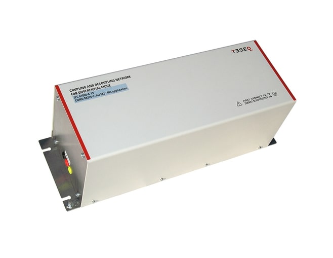
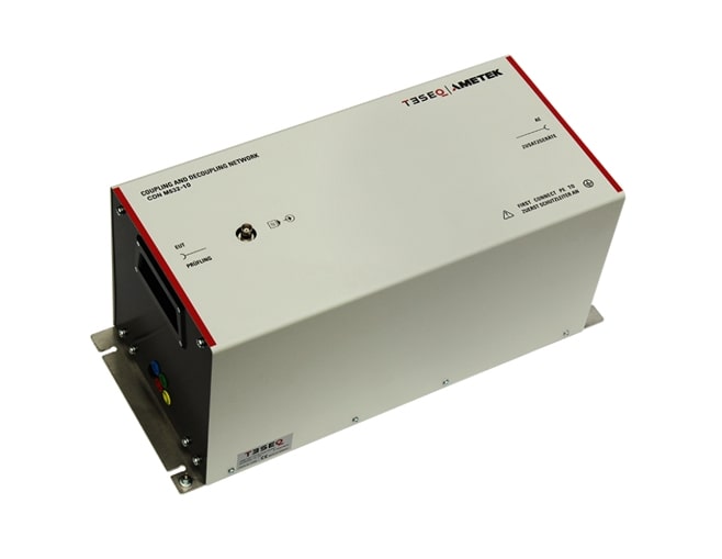
The CDND solution for the IEC/EN 61000-4-19 standard, with exceptional performance within a frequency range of 2 kHz to 150 kHz, making it the ideal choice for single-phase 3-line applications.
The CDND solution for the IEC/EN 61000-4-31 standard, specifically designed to deliver the necessary longitudinal conversion loss (LCL).
The AMETEK T series CDNs are specifically developed for unbalanced data lines. The T Series provides flexibility to choose from a variety of options based on your intended application and the number of lines involved. All our CDNs fully comply with IEC/EN 61000-4-6, ensuring seamless integration and adherence to industry standards. The T series CDNs come in two designs to accommodate different frequency ranges.
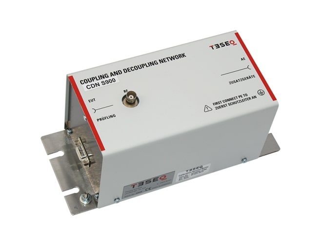
A comprehensive range of coupling/decoupling networks (CDNs) from the S series, designed and engineered to meet the stringent design and performance requirements specified by IEC/EN 61000-4-6. The S series CDNs are specifically tailored for screened data lines. AMETEK CTS offers a wide selection of choices, catering to the diverse needs of different applications and line quantities. All our CDNs fully comply with IEC/EN 61000-4-6, guaranteeing reliable performance and adherence to industry standards. Additionally, we provide two distinct designs to accommodate varying frequency ranges required for testing purposes.
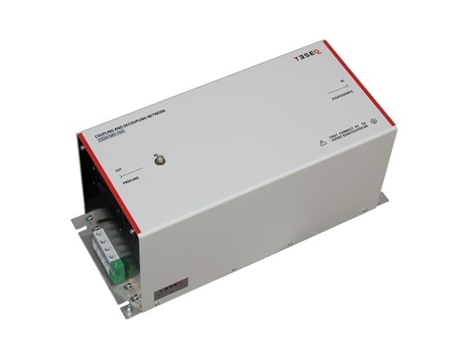
The AMETEK CTS M Series is a wide range of coupling/decoupling networks (CDNs) precisely designed and engineered to meet the design and performance requirements outlined in IEC/EN 61000-4-6. Tailored for main supply lines, the M series CDNs offer a multitude of choices based on line quantities, currents, and voltages. With a frequency range spanning from 150 kHz to 230 MHz, each CDN fully complies with IEC/EN 61000-4-6, ensuring seamless integration and adherence to industry standards.
The AMETEK CTS M Series is a wide range of coupling/decoupling networks (CDNs) precisely designed and engineered to meet the design and performance requirements outlined in IEC/EN 61000-4-6. Tailored for main supply lines, the M series CDNs offer a multitude of choices based on line quantities, currents, and voltages. Each CDN provided by Ametek fully complies with IEC/EN 61000-4-6, ensuring seamless integration and adherence to industry standards. With a frequency range spanning from 10 kHz to 80 MHz, these CDNs are versatile and suitable for applications such as NAMUR and other applicable standards.
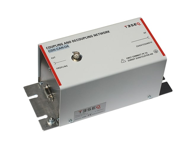
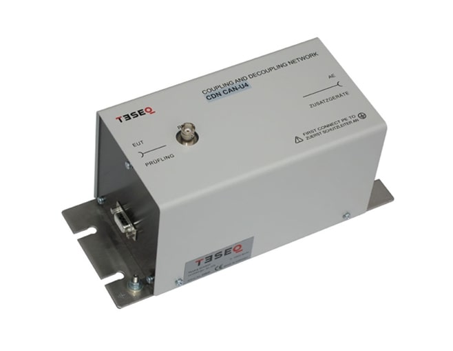
Specifically crafted for unscreened unbalanced data lines, the AF series of coupling/decoupling networks (CDNs) offers specialized designs for CAN Bus applications involving four and five lines. These CDNs fully comply with IEC/EN 61000-4-6, ensuring seamless integration and adherence to industry standards. With two frequency ranges, our CDNs deliver reliable performance across a wide spectrum of frequencies.
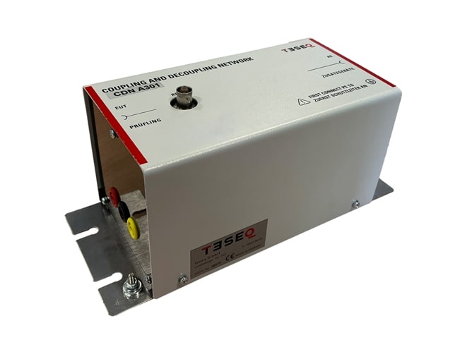
The AF series of coupling/decoupling networks (CDNs) aligns precisely with the requirements outlined in IEC/EN 61000-4-6. Specifically designed for unscreened unbalanced data lines, the AF series provides an array of options to cater to varying line quantities. With a frequency range spanning from 150 kHz to 230 MHz, all CDNs offered by AMETEK CTS fully comply with IEC/EN 61000-4-6, ensuring reliable performance and adherence to industry standards.
The AF series of coupling/decoupling networks (CDNs) aligns precisely with the requirements outlined in IEC/EN 61000-4-6. Specifically designed for unscreened unbalanced data lines, the AF series provides an array of options to cater to varying line quantities. All CDNs offered by AMETEK CTS fully comply with IEC/EN 61000-4-6, ensuring reliable performance and adherence to industry standards. With a frequency range spanning from 10 kHz to 80 MHz, these CDNs are suitable for applications such as NAMUR and other applicable standards.

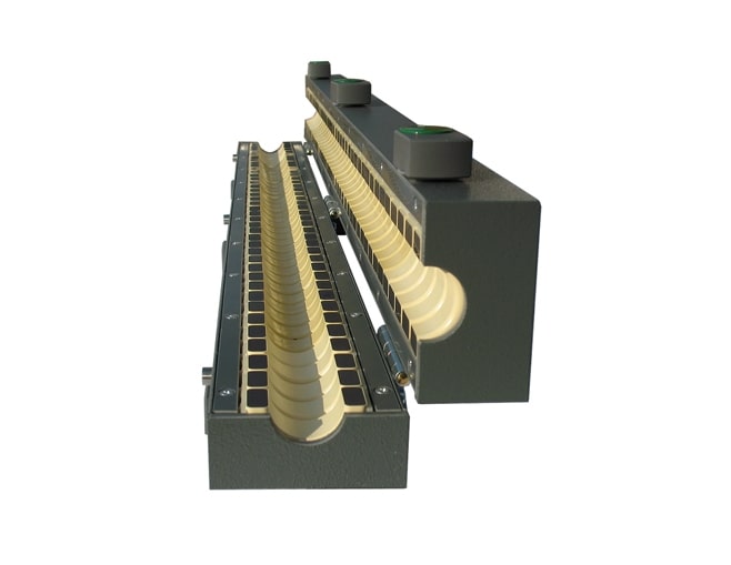
Strip Lines are made for the generation of homogeneous electromagnetic fields and specified in ISO 11452-5 and EU guidelines 95/94. The strip lines can be used for testing of electrical/electronic submodules (EUB) and their associated cables.
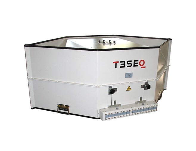
Reverberation Chambers (RCs) are modern EMC test environments in addition to the established methods like semi- or full anechoic rooms, open area test sites or GTEM cells. They can be used for emissions and immunity testing.
The transversal electromagnetic mode which can be developed in the DTEM cell, provides the opportunity for EMC testing inside the cell.
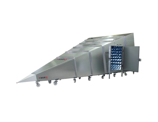
AMETEK CTS standard GTEM test packages provide a simple, guaranteed pre-defined solution for your testing needs. These complete IEC 61000-4-20 compliant systems save overall cost on components and installation. Our system engineers are ready to help you to add any customization required to the GTEM such as additional power or signal filters, air or water access, DUT manipulators etc. Please contact your local sales contact for an inquiry about Predefined GTEM Systems.
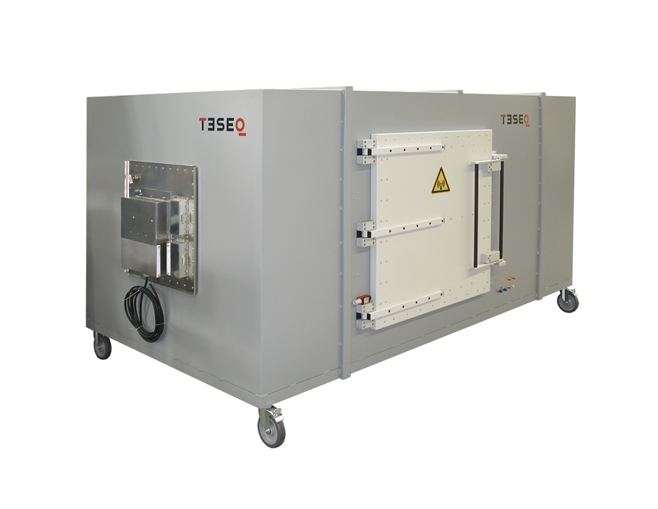
The GTEM cell is a frequency extended variant of the traditional TEM cell. Designed for EMC applications, calibration of antennas/field probes, testing and measuring of mobile phones, and other electronic devices etc.

Langer EMV-Technik GmbH also manufactures special shapes of near-field probes according to customer requirements.

The MFA family consists of four active magnetic field probes. The MFA 01 includes three magnetic field probes. The MFA 02 set consists of two magnetic field probes for low frequency measurements.

The HR family consists of an H-field probe and an E-field probe for the measurement of high-frequency RF fields up to 40 GHz during development.

The SX family consists of three H-field probes and one E-field probe. The SX1 set (two H-field probes and one E-field probe) and the SX-R 20-1 set are available.
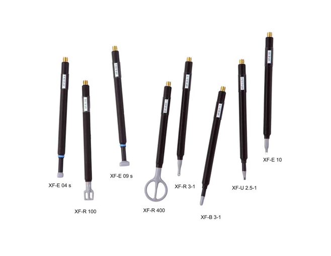
The XF family consists of four magnetic-field probes and three E-field probes. The XF1 set (four magnetic-field probes and one E-field probe) as well as customized sets are available.
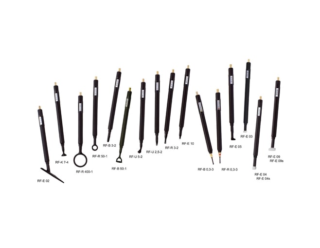
The RF family consists of nine magnetic field probes and six E-field probes, which are available in sets. These sets are optimized for different measurement tasks. We are happy to create customized sets upon request.
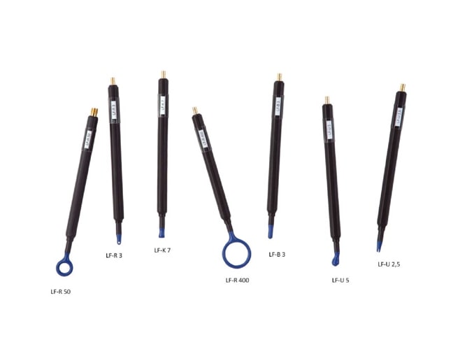
The LF family consists of seven magnetic-field probes, four of which are included in our LF1 probe set. We are happy to create customized sets upon request.

The ICS 105 IC scanner allows for measurements of high-frequency near fields above ICs. Depending on the used ICR near-field microprobe magnetic or electric fields can be measured with a measuring resolution of 50 to 100 µm. The probe can also be automatically rotated to determine the magnetic field’s direction. Optionally the ICS 105 scanner can be used for measurements above small assemblies in combination with UH-DUT universal holder and SH 01 probe holder. The IC scanner can be set up for ESD or EFT immunity tests on ICs in a few simple steps.

The RCE Series is a high-performance Near-Field Scanning System capable of 3-axis simultaneous control (X, Y, Z) for EMC/EMI debugging. This system supports a wide frequency band from 30 MHz to 40 GHz and provides ultra-precise measurement of E/H field noise on the surface of PCBs and EUTs (Equipment Under Test) with a minimum step size of 0.1 mm. Notably, it supports innovative scanning methods such as polygonal area scanning and automatic distance-keeping surface scanning of the EUT. This contributes decisively to reducing product development time by quickly and accurately identifying the noise sources of complex products.

EUT’s image change tracking and data acquisition interfaced with vehicle immunity software .

Data change tracking and image acquisition of EUT by interfacing with immunity test software for vehicles.